Adaptive Haptic Sensing Layer

-
Touchscreens are cool until they feel like dead glass. I wanted to build one that could actually feel back — a soft, flexible, printed layer that gives robots a sense of touch (and maybe emotions, but we’re not there yet).
-
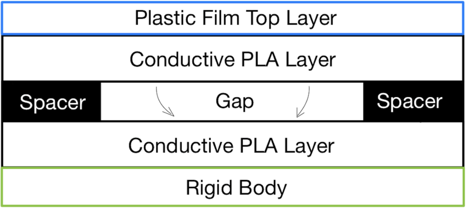
Modeled a multilayer capacitive sensor architecture in SolidWorks integrating a conductive polymer mesh, dielectric spacing, and a 3D-printed substrate. Designed electrode geometry for uniform field distribution and optimized stack height for <1 mm total deflection tolerance.
-
Conducted tactile response calibration using MATLAB and custom LabVIEW signal capture. Iteratively tuned electrode pitch, flexible substrate durometer, and print infill parameters to maximize ΔC sensitivity under multi-axis deformation while minimizing parasitic capacitance.
-
Earned departmental recognition from UC Berkeley’s College of Engineering and MSE Dept. The prototype worked, robots felt, and my printer still hasn’t forgiven me.
Adaptive Haptic Sensing Layer: Design & Modeling
CAD: SolidWorks
Design & Layout
Entire sensor was created in a single print job
No manual alignment of layers post printing
No external support (adhesives, fasteners, …)
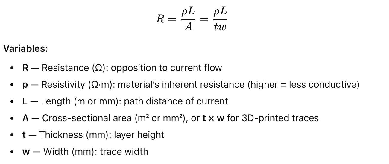
Geometric Resistance Modeling
Needed to ensure that touchpoints give reliable electrical signals (1–2.5 kΩ range for good signal detection)
Longer printed traces à more resistance
Wider printed traces à less resistance
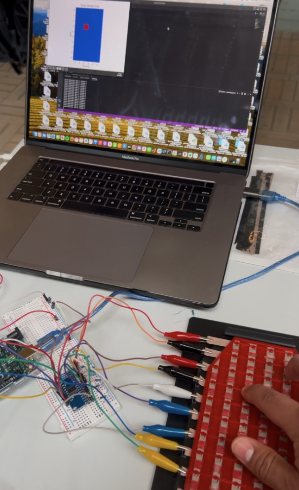
Testing & Validation
Printed test strips and full sensor arrays using Protopasta
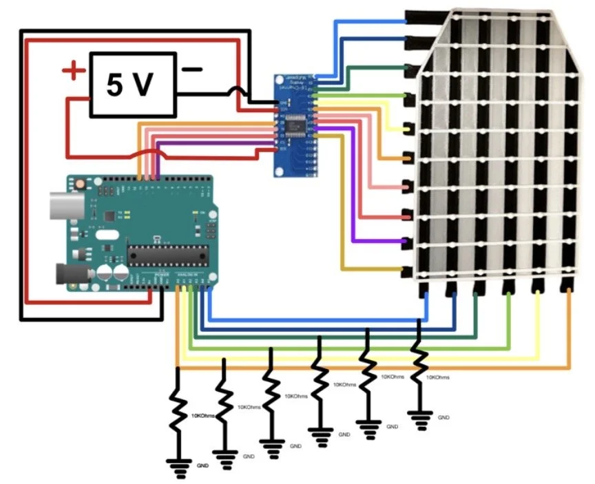
Conductive PLA + Measured current response using Arduino +INA219 current sensor
Final sensor gave a steady 1.5 mA signal per touchpoint

Adaptive Haptic Sensing Layer: Materials Selection


Adaptive Haptic Sensing Layer: Manufacturing Strategy
Chosen Process
Fused Deposition Modeling (FDM) was chosen for Multi—material capability, Fast iteration, and Lower cost (Stereolithography (SLA), and Direct Ink Writing (DIW))
Bambu Lab X1 Carbon (Single-pass printing)
Prusa MK4 (TPU- manual insertions)
Elegoo Mercury Plus (Post Processing)
Single Print
Bottom Conductive Layer (Protopasta PLA)
Polyvinyl Alcohol (PVA) Spacer 0.2 mm
Top Conductive layer
TPU or PLA bac
Manufacturing Constraints & Solutions
Conductive PLA Clogging (copper/carbon particles made the
nozzle jam) - replaced the hardened steel nozzle, lowered the speed, and turned off retraction
Prusa MK4 (earlier versions required pausing the print to manually insert layers) – switched to the Bambu lam AMS system to do it automatically
Layer peeling in the flexible sensor (the layers in the TPU versions came apart when bent) – slowed print speed, changed infill pattern, and improved bonding between layers


Adaptive Haptic Sensing Layer: Results
Sensor Performance
Consistently detected touch with 1.5 mA current
Accurate readings displayed in real time (Python GUI to Arduino)
Stable touch detection with no false positives or missed inputs
Manufacturing Impact
One step printing
No post processing
No post assembly
Avg print time: 7.5 hours
Materials cost per sensor: $27.73
Business potential
Manufacturing – single print
Customization – 72 percent reduction
Flexibility – full TPU integration
Cost - 72 .27percent reduction


Airbrake Apogee Control System

-
We wanted to build a rocket that could tell itself when to stop showing off. The goal: a flight-ready, mechanically robust airbrake system that deploys mid-air, increases drag, and regulates altitude — all without tearing itself apart at Mach 0.75
-
Designed a variable-drag flap assembly with aluminum machined components and fiberglass skins for lightweight stiffness. Used SolidWorks for parametric CAD and ANSYS for static stress and modal analysis under aerodynamic loads approximating 1.5× design pressure.
Prioritized tight tolerances in the hinge-slots (±0.05 mm) and fastener systems to maintain flap symmetry and smooth deployment. The system was engineered for rapid disassembly and reassembly during iterative ground testing, integrating a locking bolt mechanism for field tuning.
-
Conducted vibration and deployment testing to replicate flight conditions — identifying a minor hinge-slot oversize caused by tool misselection at a local vendor. Applied a root cause analysis and implemented a dual-solution fix: updated drawings with explicit tolerance callouts and added a secondary locking system.
To stay on budget, precision finishing was handled by a low-cost vendor for post-machining hole adjustments, resulting in a 35% cost reduction while maintaining flight-readiness. All adjustments were validated through pre-flight ground tests and confirmed by post-flight data.
-
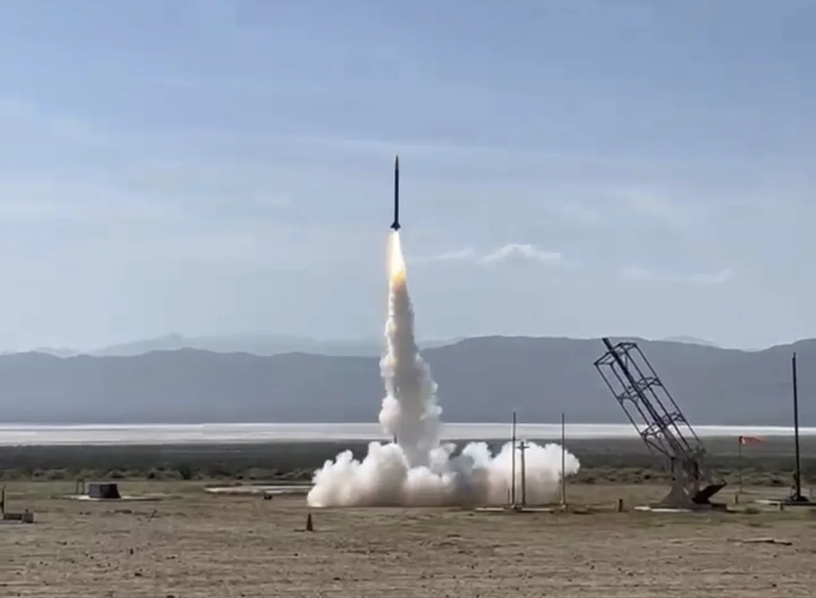
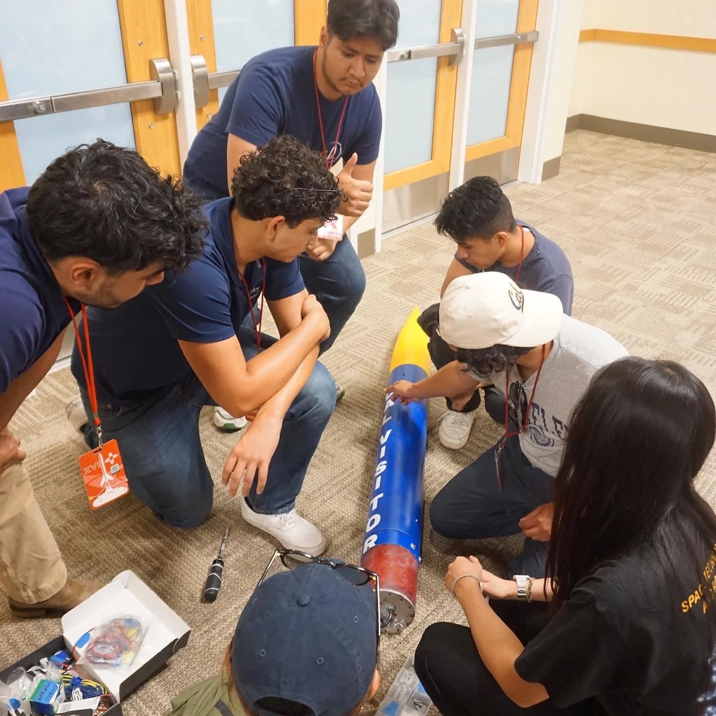
The airbrake deployed flawlessly, helping the team’s 12-ft competition rocket hit its target apogee and place 4th internationally at the Spaceport America Cup.
Turns out, thinking like a manufacturing engineer — and forgiving your machine shop — can make gravity negotiable.
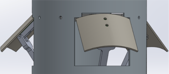
Airbrake Apogee Control System: Design & Modeling
Subsystem Architecture
Designed a deployable airbrake system to dynamically regulate rocket apogee during high-power flight at Mach 0.75.
Integrated a three-part assembly: hinge housing, deployable drag flaps, and actuator linkage to control deployment angle.
Modeled full system kinematics in SolidWorks, ensuring synchronized motion across both flaps under asymmetric loading.
Developed modular mounting to allow field disassembly and tuning between test flights.
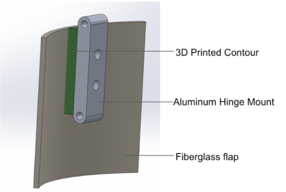
Structural Design
Used CNC-machined 6061-T6 aluminum for hinge arms and housing, optimizing for stiffness-to-weight ratio.
Defined ±0.05 mm critical tolerances on hinge-slot fits to eliminate vibration-induced oscillation.
Integrated fiberglass composite flaps to achieve aerodynamic smoothness and minimize flutter during deployment.
Modeled fastener load paths and hinge stresses to withstand >6 g acceleration and transient aerodynamic drag.
Simulation & Validation
Conducted FEA in ANSYS to analyze hinge stress, flap deformation, and modal resonance.
Simulated aerodynamic drag performance across Mach 0.3–0.8 using CFD (SolidWorks Flow Simulation).
Validated hinge torque and deployment angles through ground test rigs replicating expected aerodynamic loads.
Performed tolerance stack-up analysis to assess manufacturing deviation effects on deployment symmetry.


Airbrake Apogee Control System: Manufacturing Strategy
(Other than overworked + not paid students)
Fabrication
Machined hinge arms and frame components from 6061-T6 aluminum using 3-axis CNC milling.
Maintained ±0.05 mm tolerances on hinge slots and pivots for precise, vibration-free operation.
Cut and bonded fiberglass composite flaps using low-viscosity epoxy for a lightweight, smooth finish.
Performed manual finishing (deburring, polishing, alignment) to ensure consistent assembly fit.
Assembly
Used a bolt-through hinge design for adjustable preload and easy field maintenance.
Installed stainless-steel hinge pins and thread-locked fasteners to resist loosening under launch vibration.
Aligned assemblies with a custom test fixture, confirming flap symmetry and torque balance.
Integrated servo wiring in protected channels to prevent tangling during deployment.
Quality & Vendor Coordination
Discovered slight hinge-slot oversize during testing — traced to vendor tool mismatch.
Updated tolerance drawings and GD&T callouts, then re-machined locally to correct alignment.
Verified fit and motion through ground deployment tests simulating flight conditions.
Reduced total manufacturing cost by 35% while maintaining structural and functional performance.


Airbrake Apogee Control System: Results
System Performance
Achieved stable mid-flight deployment at Mach 0.75 with no flap flutter or oscillation.
Maintained precise hinge alignment and torque response under >6 g launch acceleration.
Demonstrated consistent drag increase during deployment, enabling controlled apogee shaping.
Manufacturing Impact
CNC + composite build held all critical tolerances after rework, ensuring smooth, repeatable motion.
Modular hinge + bolt-through design allowed full disassembly and reassembly during competition.
Local re-machining strategy cut manufacturing cost by 35% while preserving mechanical accuracy.
Flight Outcome
Airbrake system successfully regulated altitude and maintained target apogee during competition flight.
Enabled a clean, stable descent profile with no structural anomalies or hinge play.
Contributed directly to the team’s 4th Place International Finish at the Spaceport America Cup.